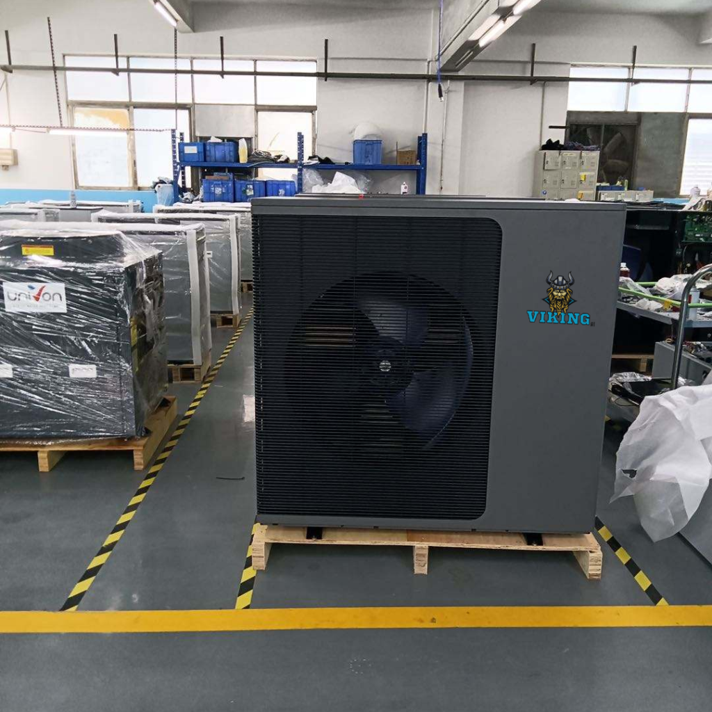
Welcome to an engaging guide through the manufacturing process of the Viking A10 heat pump with R290 refrigerant. In the following article, we will reveal, step by step, how this innovative and environmentally friendly heat pump is created, known for its high efficiency and reliability. We pay attention to every detail that ensures the quality and performance of this modern device, suitable for both residential and commercial needs.
1. The chassis is online
1.1 Fix the chassis: the chassis sheet metal is placed flat on the wooden chassis, and the chassis is aligned parallel to the edge of the wooden chassis;
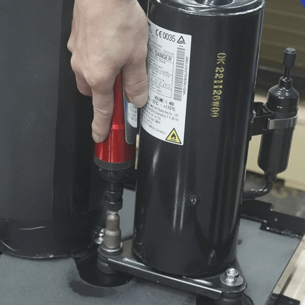
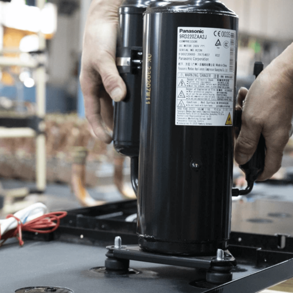
1.2 Put the foot pad:
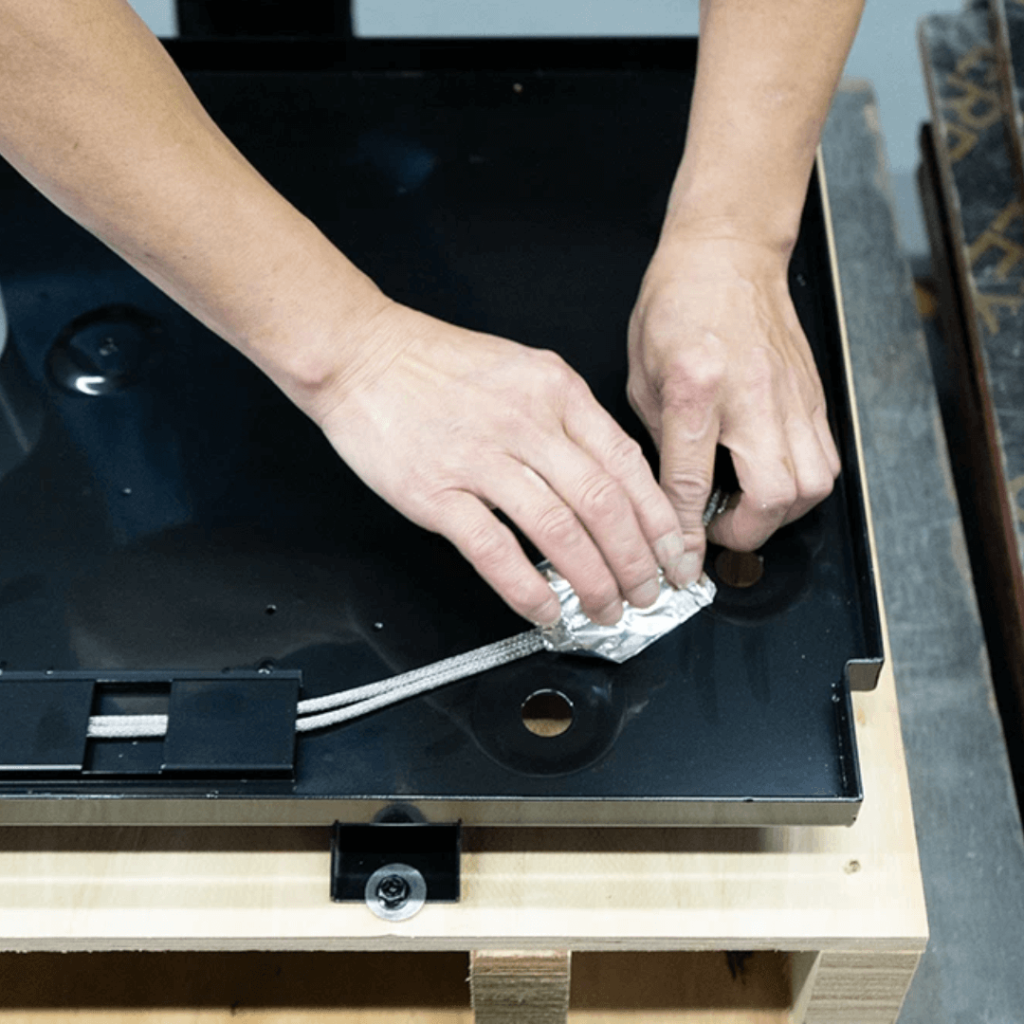
1.3 Install the chassis heating belt: the heating belt should be inserted into the chassis limit buckle
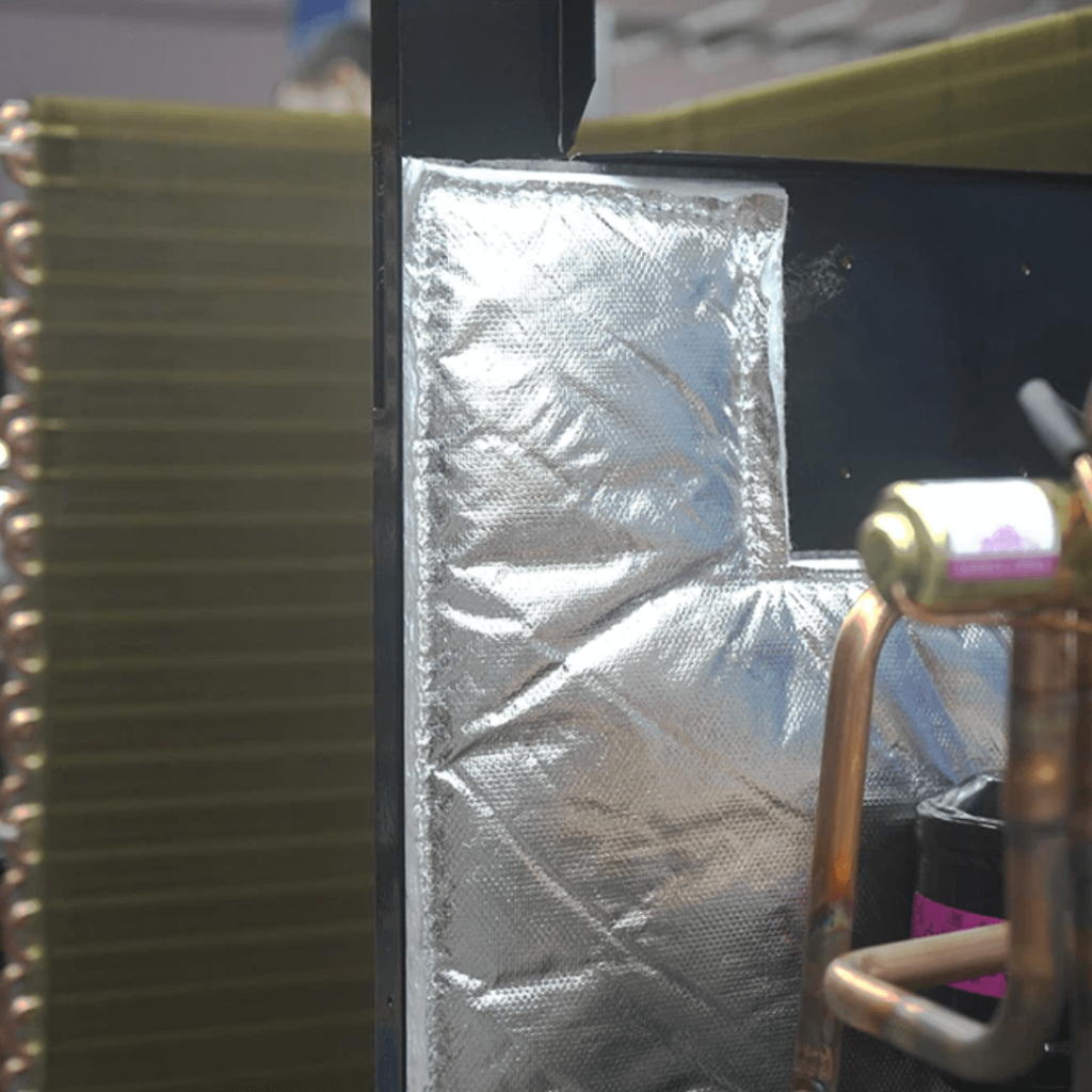
Install the center baffle and evaporator assembly.
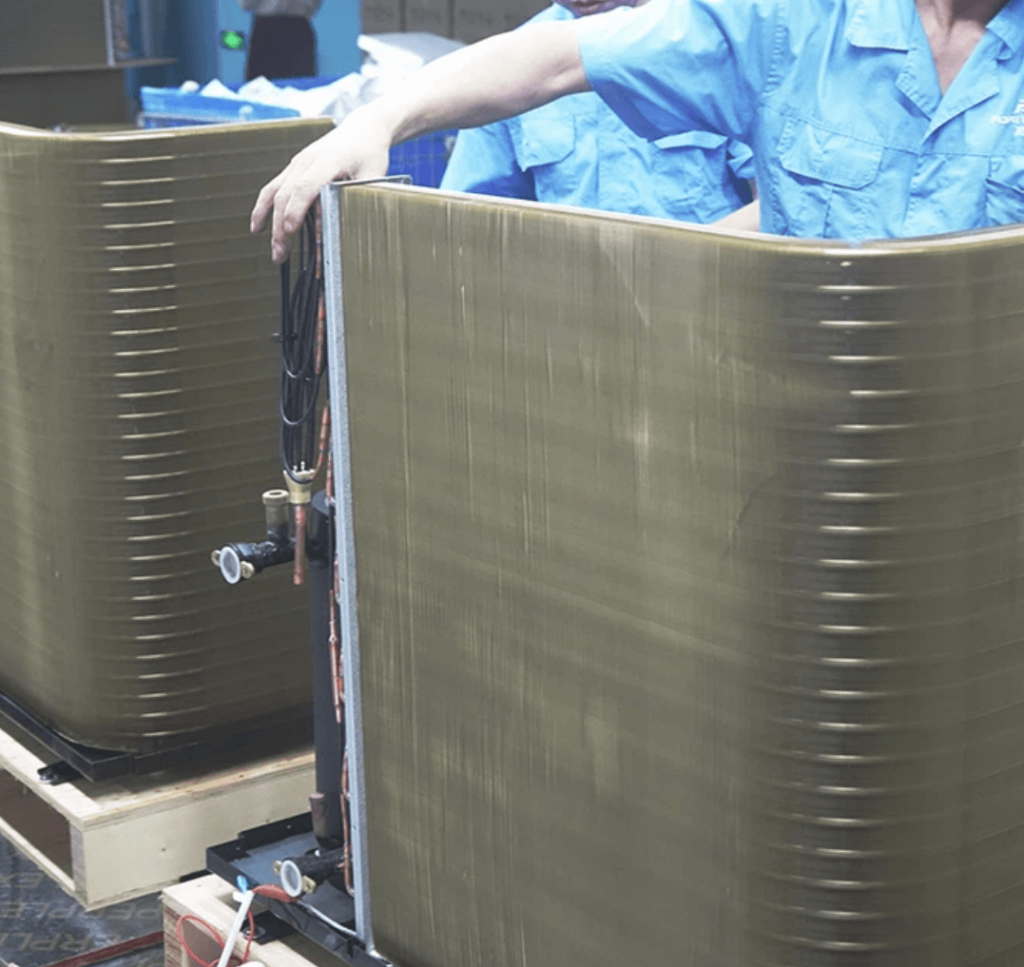
Install condenser and plate heat exchanger.
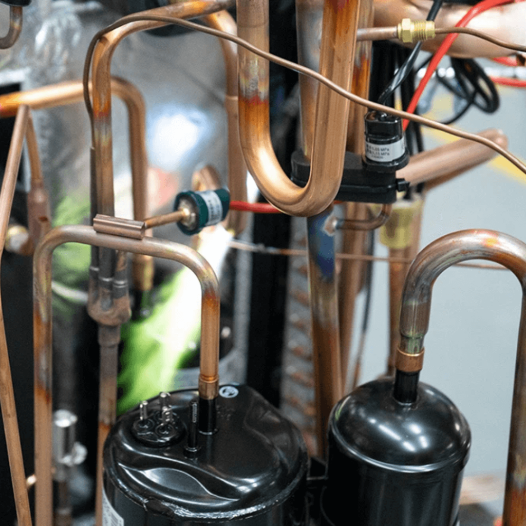
4. Pipeline connection
Pull out the pipe plug, pipe connection, and pipe welding.
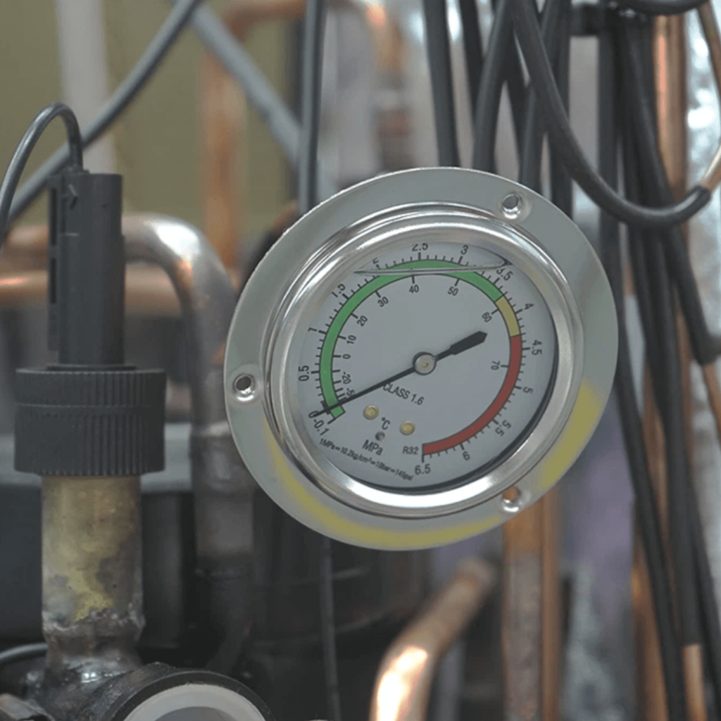
5. Leak detection: fill with nitrogen and detect leaks.
The reading should be stable at (3~4) MPa after stopping the nitrogen filling
Brush soapy water on each welding joint on the pipeline, and observe whether there are bubbles. The generation of bubbles means that there is a leak in the welding joint, and it needs to be repaired and re-inspected.
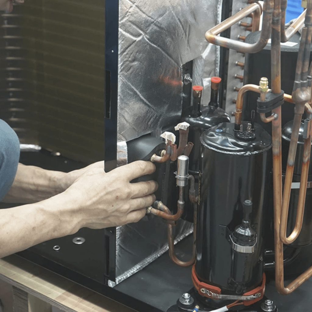
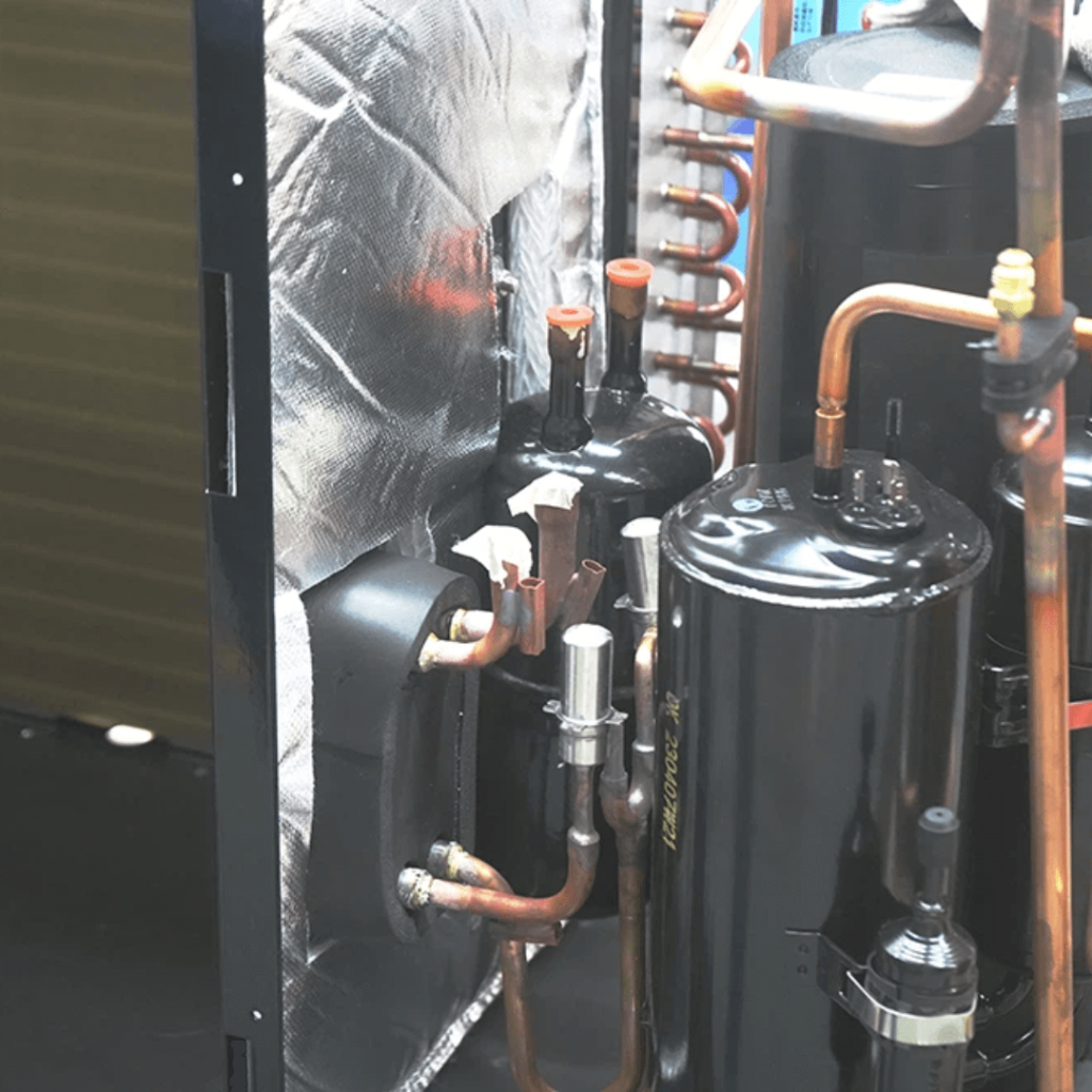
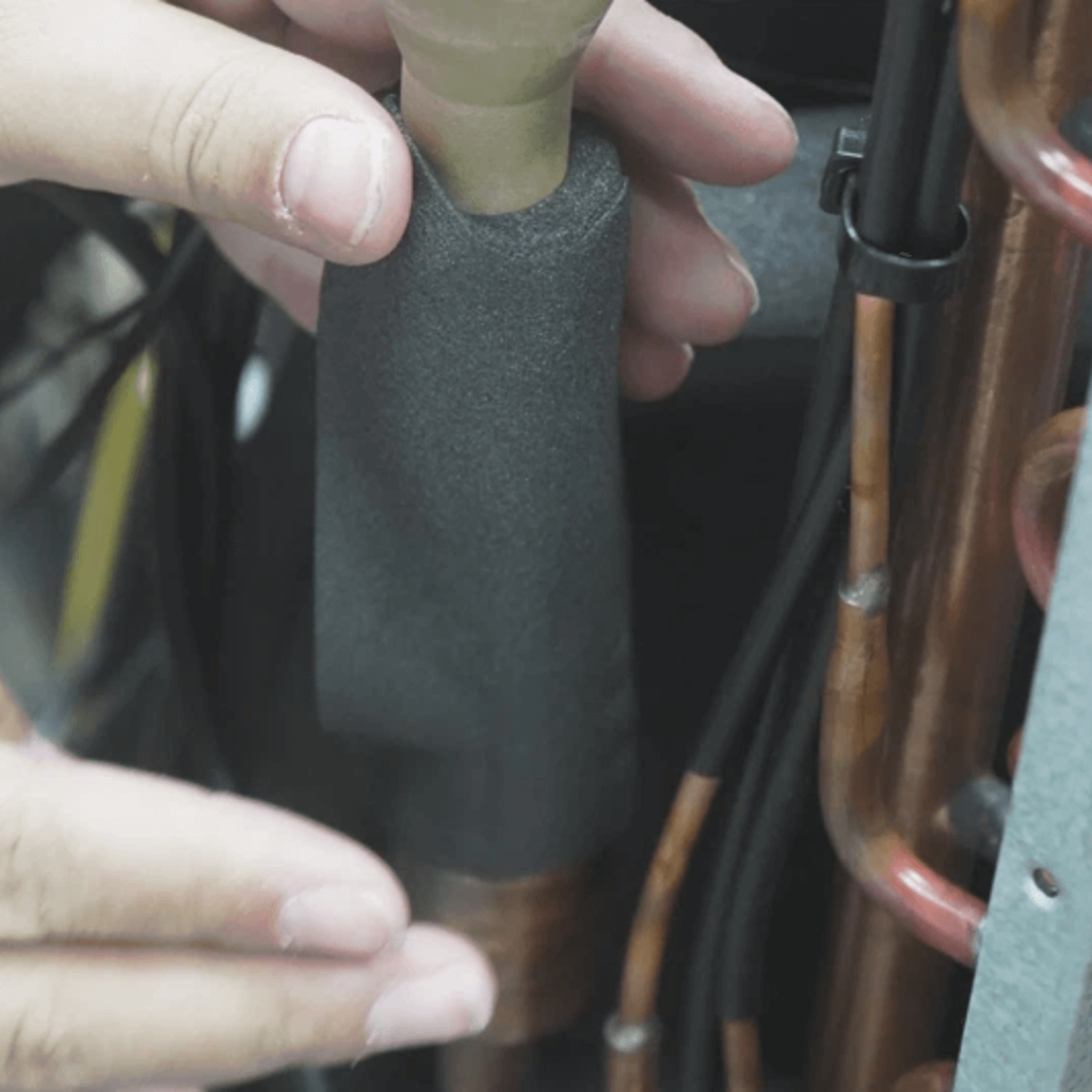
6. Pack insulation pipe and compressor silencer cotton.
Cut the insulation pipe to a suitable length according to the pipeline; the insulation pipe is tightly wrapped without looseness.
Wrap the thickened two-component sound-absorbing cotton on the compressor, and the Velcro connection is tight without loosening.
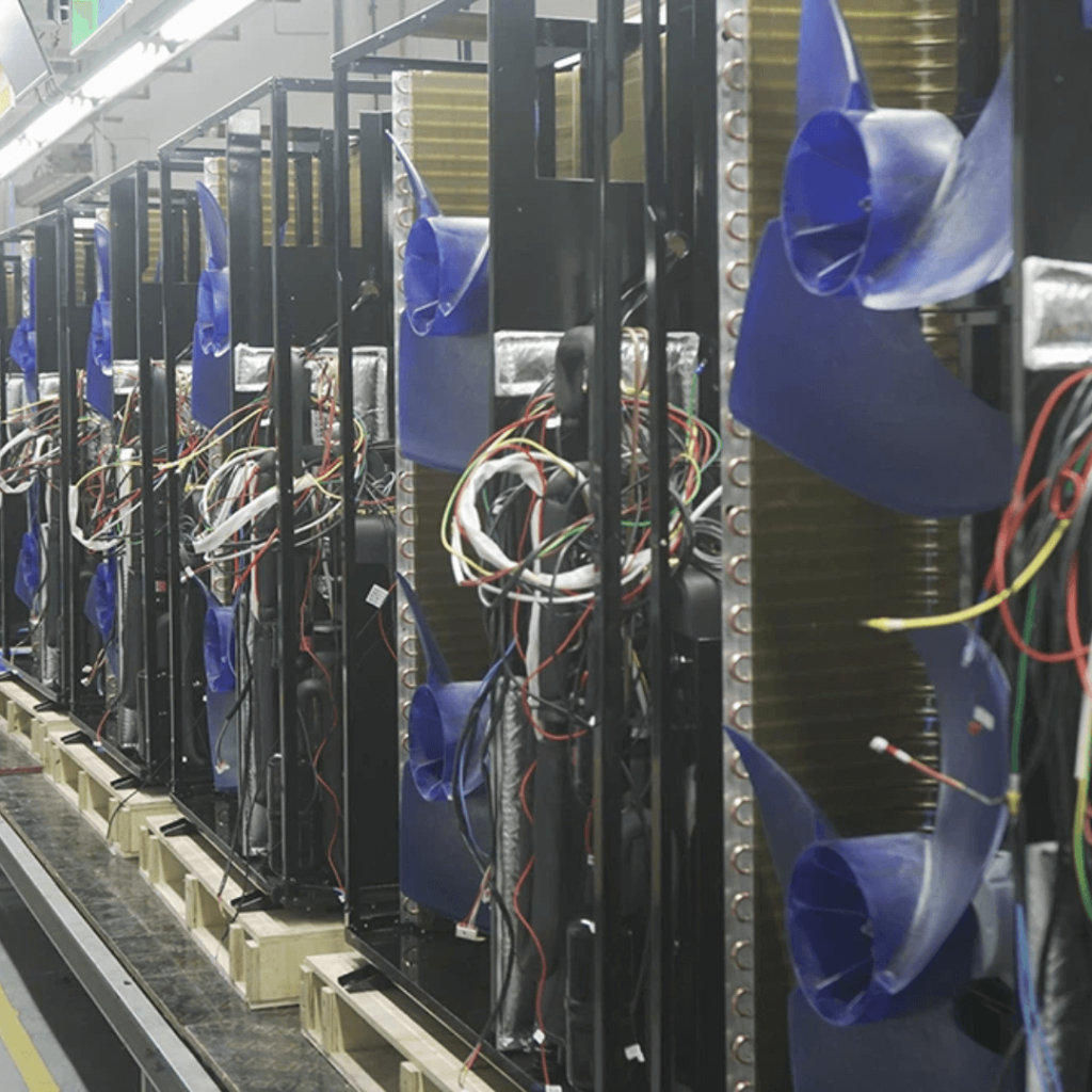
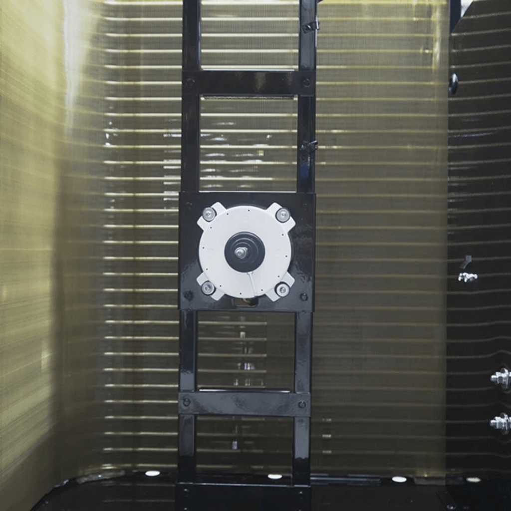
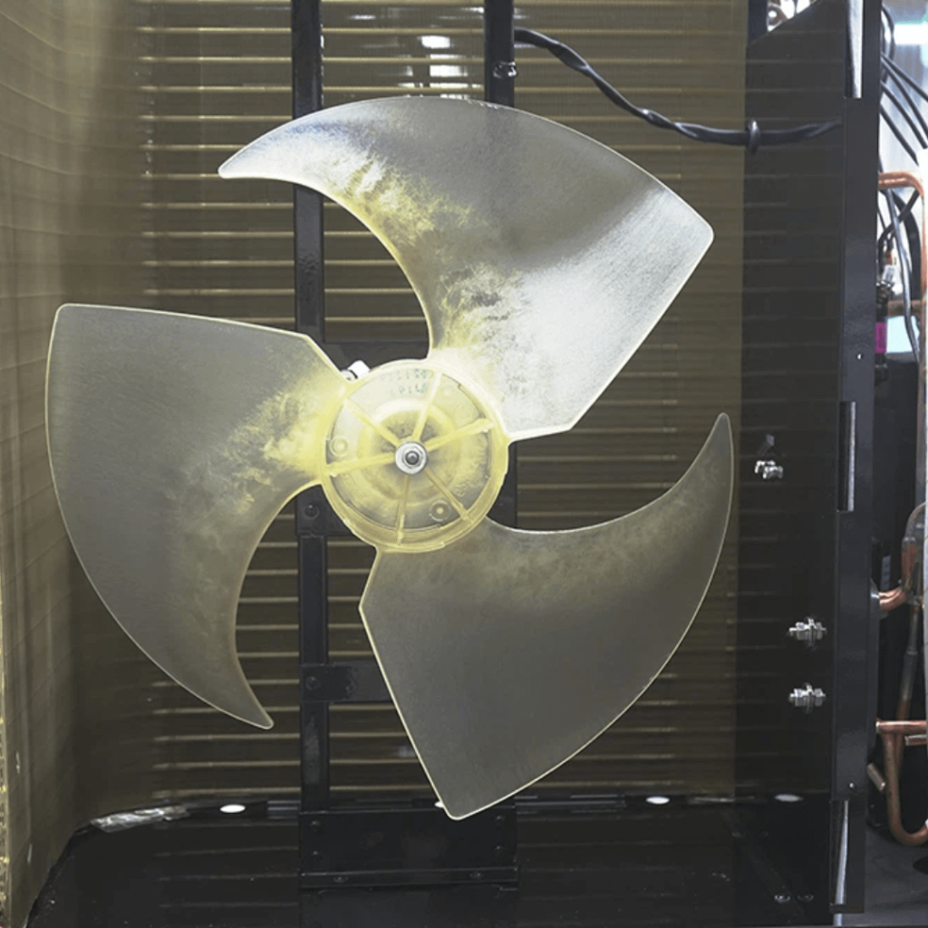
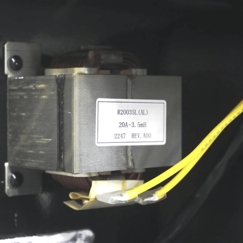
7. Install the motor, fan blades, brackets, and reactors.
Install the motor, arrange the motor wires, and put the motor wires into the bracket slot.
After the installation is fixed, draw a line at the nut to check whether it is tight.
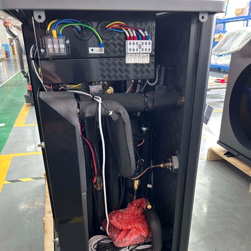
8. Intubation warm wire, Wiring, management, and Install fuselage parts.
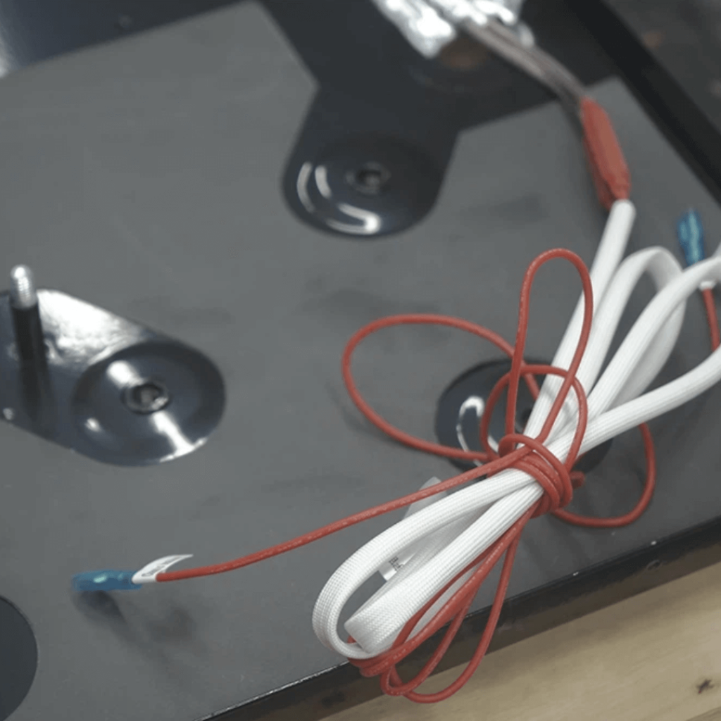
Intubation warm wire
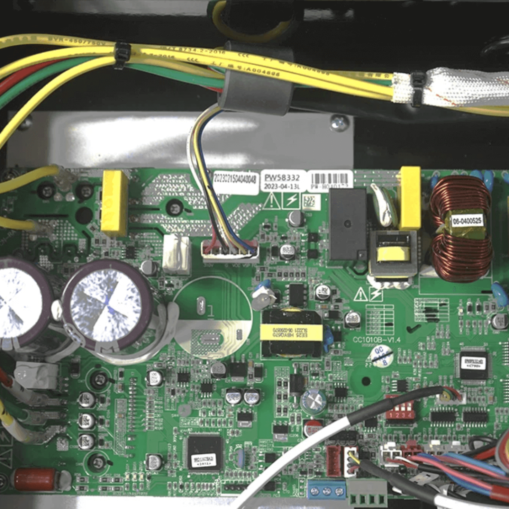
Install electric control components
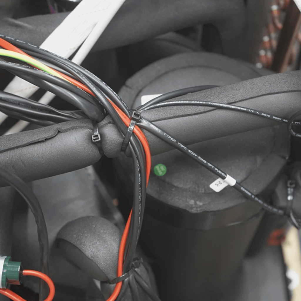
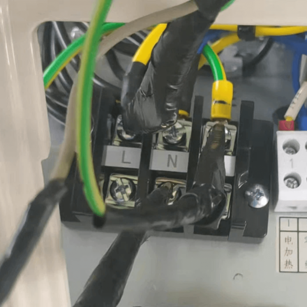
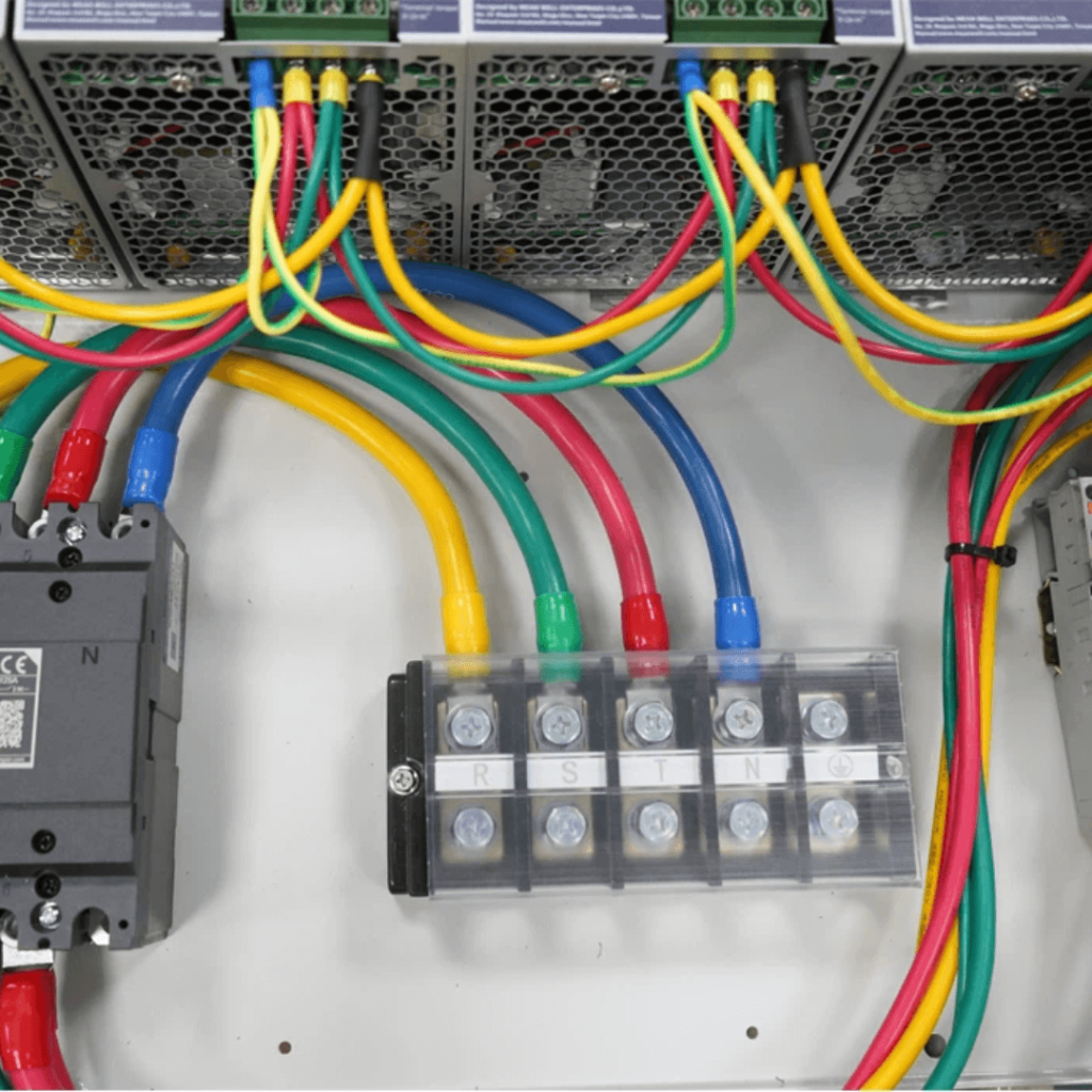
System wiring: An anti-static wrist strap is required for wiring.
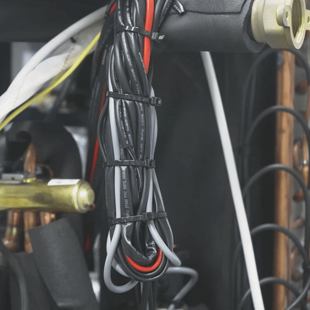
Line management:
Separate the strong and weak electricity, and then tie the wires with cable ties;
Note that the wiring should not touch the sheet metal or the copper pipe. If it must pass through the copper pipe, it must be separated by an insulation tube;
When tying the wires, the wires should be moderately tight and should not be too tight.
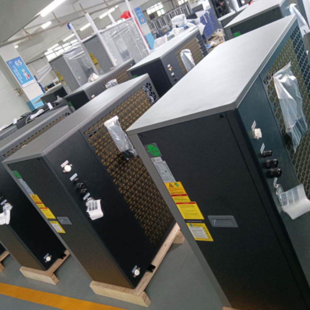
Install fuselage panels and control components.
9. Vacuumizing and charging refrigerant
① Connect the vacuum equipment and the machine with the leather tube connection tool;
② Start the vacuuming operation, the vacuum degree should be <30Pa, and record the actual value on the process card.
Charge refrigerant:
① Confirm whether the refrigerant model required by the process card is consistent with the actual situation, and set the charging amount according to the model requirements;
② Connect the refrigerant charger and start the equipment charging operation;
③ After the refrigerant charge reaches the set value, remove the connecting pipe tooling and lock the needle valve cap.
10. Safety inspection and Performance testing.
① Select the corresponding security inspection parameters according to the parameter table;
②The firewire of the security inspection instrument is connected to the L terminal of the terminal block, the neutral wire is connected to the N terminal, the ground wire is connected to the ground wire end, and the clip is clamped on the copper pipe (an anti-static bracelet is required for security inspection.)
③Start the test, and record the value on the process card after the test is passed.
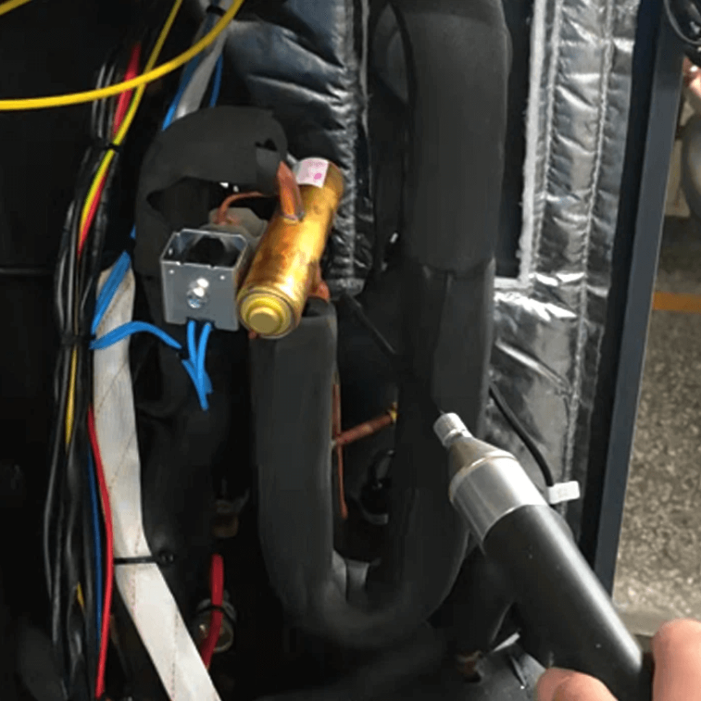
Halogen leak detection
①Use a suction gun to check for leaks on each welding joint of the unit one by one. The probe is 2-5 cm away from the welding joint, and the moving speed is 2 cm per second.
②The fan is not allowed to face the unit during the leak detection process.
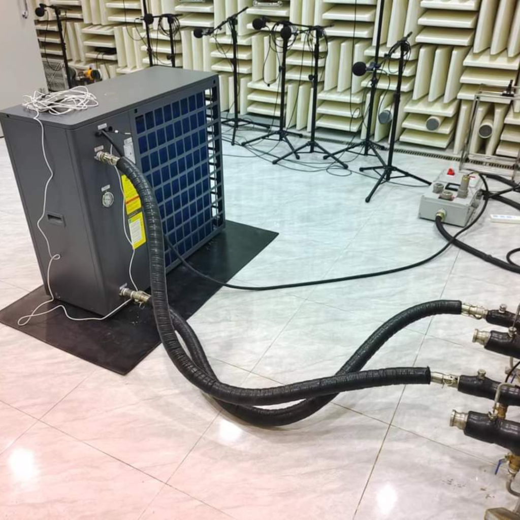
Performance testing ① Connect the waterway and the circuit according to the diagram on the left; ② Power-on test, after stable operation for more than 5 minutes, check whether the unit is running abnormally, the exhaust gas return is stable, whether there is abnormal noise in the unit, whether there is abnormal vibration in the pipeline, water leakage, and other problems; ③Record the test data of stable operation on the process card.
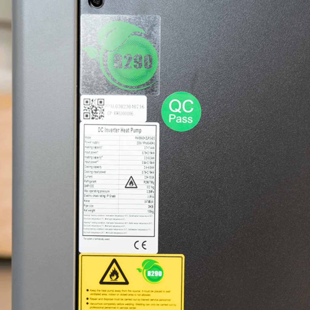
11. Paste the panel label and Accessories.
The label must not be missed or reversed, and there are no obvious air bubbles.
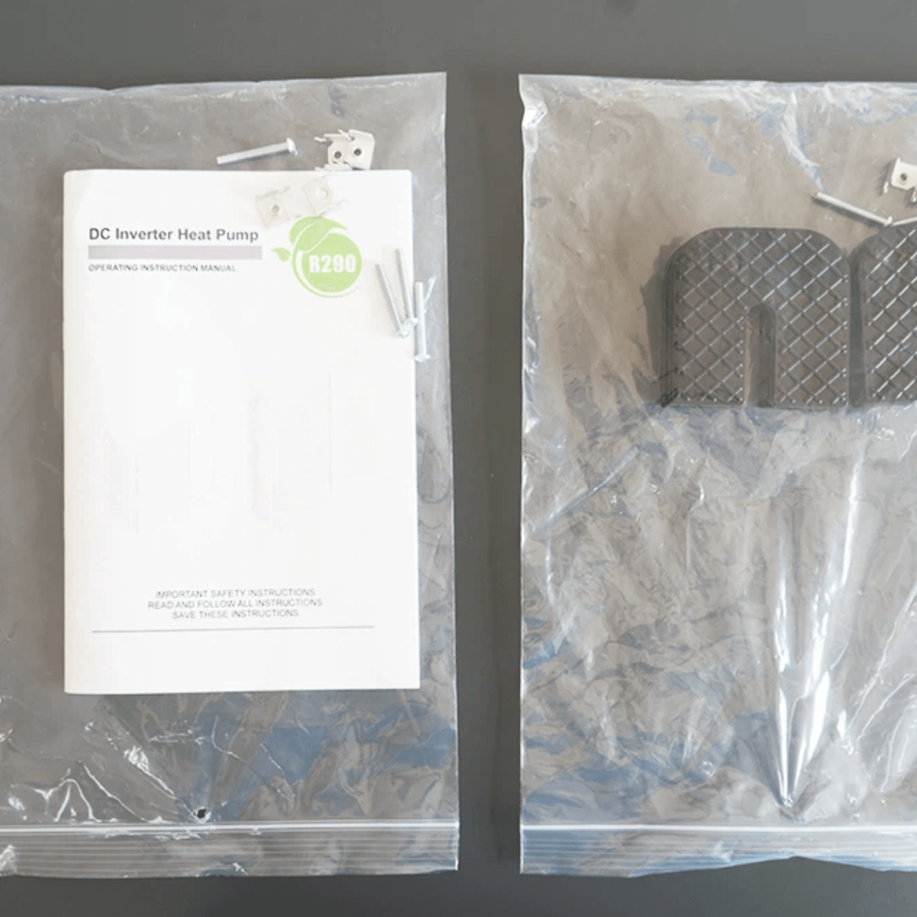
Bag accessories, bag rubber blocks
Put the manual into the PE transparent tape,
Put the rubber block into the PE transparent belt, and stick it on the machine with adhesive tape.
12. Final testing
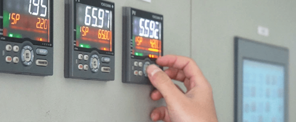
Our testing procedures include performance tests under extreme temperatures, resistance to humidity, and long-term stability. We also utilize certified measuring devices to verify the performance and efficiency of each heat pump. Our goal is to ensure reliable and efficient heat pumps that meet the needs and expectations of our customers.